|
Logbook from 3 December 2001 to 23 February 2002
mon 3-Dec-2001
- Shot from 1011203001 to 092.
tue 4-Dec-2001
- Shot from 1011204001 to 008.
- The shelf with the amplifiers have been rotated 90 degrees so that all the
inputs of amplifiers are pointing to the flange of the diagnostic.
- Changed the full scale of two digitizers to +/- 10V (SCADT-001 and 002, slot 14 and 15).
- The knob for inserting/extracting the probe have been machined and installed; now it should be easier to move the probe in and out.
- A Femto amplifier has been used to test all Fischer connectors on the flange of the used diodes (these feedthroughs seem a little bit "loose") so that no saturation occurs.
- Test shot (without discharge): 1011204008
- Talked to Mikhail and Sarff regarding the shielding: they do not think shielding will help. No decision has been made at this point.
- Vacuum problems. In order to take the knob off, the probe was extracted, the VAT was closed and a clamp for a vacuum seal has been rotated (this clamp is for the NW40 vacuum connection below the ~4 inch (100 mm) connector cylinder; the vacuum was not break; the clamp was right above the knob used to turn the threaded rod when the probe is extracted or inserted). During the insertion process, the following happens:
- (a) before opening the VAT, P=9.44X10^-7 Torr
- (b) after open VAT and insert the probe, P=1.02X10^-6 Torr for a long time.
- We do not know whether it is outgassing or leaking. Under suggestion of Sarff the probe has been fully extracted and the VAT closed. The probe has been pumped overnight (rough vacuum).
wed 5-Dec-2001
- Shot from 1011205001 to 093.
- Leak detection this morning indicated that one (or more) Fischer connector feedthrough is leaking. A few tests have shown that the #17 feedthrough is leaking on the center connector part (not the O-ring seal). We do believe that frequent connection and disconnection (or moving and wiggling for improving the noise problems) are the cause of the leak.
thu 6-Dec-2001
- Shot from 1011206001 to 116.
- The feedthrough for diode #17 has been replaced. The device is back in operation.
- The signals from HXS amplifiers are now saturated at a level slightly above 6 volts (sample Shot 1011206096). We believe that the amplifiers may have power supply voltages around +/-6 V, which limit the maximum output voltages.
fri 7-Dec-2001
- Shot from 1011207001 to 100.
sat 8-Dec-2001
- Shot from 1011208001 to 101.
sun 9-Dec-2001
mon 10-Dec-2001
- Shot from 1011210001 to 119.
- Shot 1011210001 to 013 are shots with ground on the digitizer side.
- It has confirmed that the HSX amplifiers are saturated at ~6.5 V. The amplifiers have not been turned on after we removed an amplifier to test the 6.5 V limit, so the SXR signals are not available the whole day.
- All Fischer connectors have been checked with the Femto amplifiers so they were not saturated. Before the grounding rearrangement this morning, all 8 channels have been checked again, and they remain unsaturated with the Femto amplifiers, at gains up to 10^9 V/A.
tue 11-Dec-2001
- Shot from 1011211001 to 010.
- Two more diodes have been connected to the digitizer, diode 1 and 3; the arrangement is:
diode 1 ---> cable10 ---> Joerger slot 15, ch4 ---> sxr_extr_0 (10^8 gain)
diode 3 ---> cable11 ---> Joerger slot 14, ch1 ---> sxr_extr_1 (10^8 gain)
Shot 1 --> no data; shot 2 to 4 --> diode 3 on; shot 5 to 10 --> diode 1 on.
- On Thursday, I will try to use isolated outputs and ground the outputs of amplifiers to the digitizer side and the inputs (diodes) side to MST.
- About noise suppression for diodes. John Sarff thinks that the shielded twisted pair might be better. Several people did not seem to believe that shielding the amplifiers and cables will help the situation (single diode system does not have shielding either).
wed 12-Dec-2001
- Shot from 1011212001 to 103.
- Today's measurements (Wednesday) are with grounding on the digitizer side. The initial assessment of moving the ground from the MST side to the digitizer side seems to create more noise. (compare shots 1011212080 and 1011206041, both are 425 kA shots).
thu 13-Dec-2001
- Shot from 1011213001 to 078.
- The configuration has been changed today, the ISO outputs of the "HSX" amplifiers have been used and both sides have been grounded. Diode 7,9,11, Femto, are not used.
fri 14-Dec-2001
- Shot from 1011214001 to 081.
- Again, diode 7,9,11 (Femto) are not used.
- No useful signals today.
sat 15-Dec-2001
- Shot from 1011215001 to 080.
- Femto, diode 7,9,11 not used.
- Signals with high noise.
sun 16-Dec-2001
- Shot from 1011216001 to 047.
- Femto, diode 7,9,11 not used.
mon 17-Dec-2001
- Shot from 1011217001 to 103.
- Somehow the cable 16 (diode 13) and cable 17 (diode 15) have been switched. So the cable 16 was for diode 15 and 17 for diode 13 (you can also judge from the signal heights. This mistake has been corrected on 2002 Jan 14.
- Starting from the shot 1011217026 (inclusive) the amplifier gains are:
|
diode
|
1
|
3
|
5
|
7
|
9
|
11
|
13
|
15
|
17
|
19
|
|
cable
|
10
|
11
|
12
|
13
|
14
|
15
|
17
|
16
|
18
|
19
|
|
logical
|
0
|
1
|
2
|
3
|
4
|
5
|
7
|
6
|
8
|
9
|
|
gain 10^
|
8
|
8
|
8
|
8
|
8
|
8
|
7
|
7
|
8
|
8
|
and the Femto amplifiers are used too.
tue 18-Dec-2001
- Shot from 1011218001 to 004.
- The diagnostic was disconnected to try to isolate it from the MST vacuum vessel.
- Shot 003 and 004 are (I think) a measurement of the noise without the diagnostic, that is without the array of diodes and the cables from the array to the flange.
wed 19-Dec-2001
- Shot from 1011219001 to 057.
- We had several problems to insulate the probe housing (manipulator) from
the MST vessel.
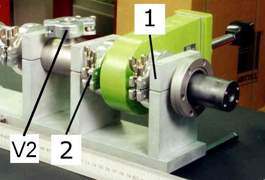
- The bolts used to connect the short spool to the MST vessel were sticking out a little bit too much so that the support (1) plates was making contact with one or more bolts. We had to put a thin mylar sheet (transparency sheet) between them.
- The blue paper used for the amplifiers is too thick. We have little tolerance on the clamp. So this paper has not be used to isolate the probe.
- We tried to use two layers of mylar sheet instead of the blue paper; but doing so we were slightly mis-aligning the probe. We managed to put the bolts in for the clamp (1). Since we had bigger gap between the two halves of the clamp and the bolts were short (there were about 2-3 turns of threads on the fixed half of clamp (1)), we had to start to tighten the clamp when there were only about one turn thread in. We STRIPPED the threads of one of the two threaded hole. So we can no longer tighten the clamp (1) anymore. In the meantime, we have used duct tape to fix the clamp instead of the bolts.
- Since we had problems, we could not put the probe in its measuring position. Anyway, we have insulated the probe housing (we checked that the probe was not touching the MST porthole) and used grounded BNC connector panels on the digitizer side. At least, we could check the noise. Dan Den Hartog pointed earlier that the result may not be good because the capacitive coupling (due to small insulating gaps). For the HXR detector, they initially used thin layer insulator between the detector ground and the manipulator, and that still gave them lots of noise. They later insulated the manipulator through the insulating NW40 seal and got good results.
- The results revealed the worst noise levels ever: see shots 1011219020 (no discharge) and 1011219057 (270 kA Ip).
thu 20-Dec-2001
- Shot from 1011220001 to 120.
- The probe has been inserted to its measuring position.
- The noise we had is 12 kHz oscillations which existed even without discharge. This was something new. We also connected the manipulator to MST (using a regular NW40 aluminum clamp for (2)) and kept the diagnostic grounded on the digitizer side. The same oscillations were still there. We do not think we had that before.
- The signals cannot be used, there is really a lot of noise.
fri 21-Dec-2001
- Shot from 1011221001 to 046.
- From shot 1011221020 the diagnostic has been disconnected to replace the support (1) with a new, isolated, one.
sat 22-Dec-2001
- Shot from 1011222001 to 014.
- Diagnostic disconnected.
- We have replaced the support (1) with the delrin one, in order to get a better isolation from MST (instead of using mylar sheets).
sun 23-Dec-2001
- Shot from 1011223001 to 028.
- Diagnostic disconnected.
mon 24-Dec-2001
- Shot from 1011224001 to 124.
- Diagnostic disconnected.
tue 25-Dec-2001
wed 26-Dec-2001
- Shot from 1011226001 to 007.
- Diagnostic disconnected.
thu 27-Dec-2001
- Shot from 1011227001 to 155.
- Diagnostic disconnected.
fri 28-Dec-2001
- Shot from 1011228001 to 083.
- Diagnostic connected with the new delrin support (1). The noise is still present, and we think even larger than before. This is the worst configuration for the probe. Filtering the signals we note that the edge chords see a constant value, whereas in the core there are no data.
sat 29-Dec-2001
sun 30-Dec-2001
mon 31-Dec-2001
tue 1-Jan-2002
wed 2-Jan-2002
thu 3-Jan-2002
- Shot from 1020103001 to 148.
- The SXR data are still noisy, but after a filtering the signals are more or less centered around 0.
fri 4-Jan-2002
sat 5-Jan-2002
sun 6-Jan-2002
mon 7-Jan-2002
- Shot from 1020107001 to 054.
- No useful data; actually there were no plasma this day.
tue 8-Jan-2002
wed 9-Jan-2002
- Shot from 1020109001 to 062.
- PPCD shots! The SXR data often saturate, and starting from the shot 048 the three Femto (diode 7,9,11) have been disconnected (?). Only a few shots can be considered for the analysis.
thu 10-Jan-2002
- Shot from 1020110001 to 039.
- Femto (diode 7,9,11) disconnected.
fri 11-Jan-2002
- Shot from 1020111001 to 063.
- Femto again connected.
- PPCD shots. Often the SXR signals are saturated.
sat 12-Jan-2002
sun 13-Jan-2002
mon 14-Jan-2002
- Shot from 1020114001 to 090.
- Starting from the shot 1020114049 (inclusive) the amplifier gains are:
|
diode
|
1
|
3
|
5
|
7
|
9
|
11
|
13
|
15
|
17
|
19
|
|
cable
|
10
|
11
|
12
|
13
|
14
|
15
|
16
|
17
|
18
|
19
|
|
logical
|
0
|
1
|
2
|
3
|
4
|
5
|
6
|
7
|
8
|
9
|
|
gain 10^
|
8
|
8
|
8
|
7
|
7
|
7
|
7
|
7
|
8
|
8
|
and the cable 16 and 17 have been switched back to the original configuration (cable 16=diode 13 and cable 17=diode 15).
- No SXR data.
tue 15-Jan-2002
- Shot from 1020115001 to 011.
- No SXR data.
wed 16-Jan-2002
- Shot from 1020116001 to 041.
- No SXR signals present.
thu 17-Jan-2002
fri 18-Jan-2002
- Shot from 1020118001 to 068, but all without plasma.
sat 19-Jan-2002
sun 20-Jan-2002
mon 21-Jan-2002
- Shot from 1020121001 to 085. This day was dedicated entirely to out diagnostic, and a number of tests have been performed.
- All of the tests have been done with detectors extracted, housing insulated from MST, and system grounded on the digitizer side. We also used an isolation transformer for the 115 AC power line. We went back to the original configuration (diagnostic connected to the MST vessel and electronics grounded on the vessel too) after the experiments and we asked another day for setup run on next Friday (today's plasma was bad due to a leak).
- One thing interesting is that using a single diode does not reduce the noise significantly if the VAT is open (shots 1020121079 and 082, cable 12, diode 5) but significant if the VAT is closed (shots 1020121080 and 081, cable 12, diode 5).
- Also connecting the Lemo connectors outside on the flange (shot <1020121070) does not increase the noise level. No ground loop are observed.
- The noises among the HSX detectors (or among Femto amplifiers) during the plasma shots are coherent. The coherency between HSX and Femto amplifier noises is also high but lower than the noises from the same kind of amplifiers.
- During the PPCD shots, the noise levels are reduced (see shot 1020109040).
tue 22-Jan-2002
wed 23-Jan-2002
- Shot from 1020123001 to 007, all without plasma.
thu 24-Jan-2002
fri 25-Jan-2002
- Shot from 1020125001 to 061. Plasma current up to 450kA.
- SXR signals with some noise, but never saturated.
sat 26-Jan-2002
sun 27-Jan-2002
mon 28-Jan-2002
- Shot from 1020128001 to 057. Some PPCDs.
- The amplifier gains have been changed:
|
diode
|
1
|
3
|
5
|
7
|
9
|
11
|
13
|
15
|
17
|
19
|
|
cable
|
10
|
11
|
12
|
13
|
14
|
15
|
16
|
17
|
18
|
19
|
|
logical
|
0
|
1
|
2
|
3
|
4
|
5
|
6
|
7
|
8
|
9
|
|
gain 10^
|
8
|
8
|
7
|
7
|
6
|
6
|
6
|
7
|
8
|
8
|
- We are a little bit puzzling why the oscillation of part of the signals on the opposite symmetric sides do not reverse the phase (as Be_1 and Be_2 do). Maybe the oscillations are from the noise rather than from SXR.
tue 29-Jan-2002
wed 30-Jan-2002
- Shot from 1020130001 to 080, all without plasma.
thu 31-Jan-2002
- Shot from 1020131001 to 042, all without plasma.
fri 1-Feb-2002
- Shot from 1020201001 to 059.
- PPCD! All signals NOT saturated.
- The amplifier gains have been changed. From shot 001 to 044:
|
diode
|
1
|
3
|
5
|
7
|
9
|
11
|
13
|
15
|
17
|
19
|
|
cable
|
10
|
11
|
12
|
13
|
14
|
15
|
16
|
17
|
18
|
19
|
|
logical
|
0
|
1
|
2
|
3
|
4
|
5
|
6
|
7
|
8
|
9
|
|
gain 10^
|
8
|
8
|
7
|
7
|
7
|
7
|
7
|
7
|
8
|
8
|
and for 045 to 059 they are:
|
diode
|
1
|
3
|
5
|
7
|
9
|
11
|
13
|
15
|
17
|
19
|
|
cable
|
10
|
11
|
12
|
13
|
14
|
15
|
16
|
17
|
18
|
19
|
|
logical
|
0
|
1
|
2
|
3
|
4
|
5
|
6
|
7
|
8
|
9
|
|
gain 10^
|
8
|
8
|
7
|
7
|
7
|
7
|
7
|
7
|
7
|
8
|
sat 2-Feb-2002
sun 3-Feb-2002
- Shot from 1020203001 to 049; plasma current 200-250kA.
mon 4-Feb-2002
- Shot from 1020204001 to 026.
tue 5-Feb-2002
wed 6-Feb-2002
- Shot form 1020206001 to 067.
- Today's gains for shots 001-067 (same as Jan 25. setting):
|
diode
|
1
|
3
|
5
|
7
|
9
|
11
|
13
|
15
|
17
|
19
|
|
cable
|
10
|
11
|
12
|
13
|
14
|
15
|
16
|
17
|
18
|
19
|
|
logical
|
0
|
1
|
2
|
3
|
4
|
5
|
6
|
7
|
8
|
9
|
|
gain 10^
|
8
|
8
|
8
|
7
|
7
|
7
|
7
|
7
|
8
|
8
|
- Amplifier for cable 12, diode 5, was not powered until shot 025.
- Shots 045-067 was with probe rotated 90 deg. counter-clockwise.
- The discharge current has been varied to get large enough signals for all the diodes.
- With present gains and filter, signals are often small for standard 400kA discharge. Thinner filter is probably required for low current standard discharges in the future (current one is 25um nominal and 30um measured). We can also decide to use the diagnostic mainly during enhanced confinement discharges, where 30um could be too thin!
thu 7-Feb-2002
- No shot.
- The diode array has been rotated back to have poloidal resolution.
fri 8-Feb-2002
- Shot from 1020208001 to 075; no PPCD were made.
- The amplifier gains have been changed, starting from shot 001:
|
diode
|
1
|
3
|
5
|
7
|
9
|
11
|
13
|
15
|
17
|
19
|
|
cable
|
10
|
11
|
12
|
13
|
14
|
15
|
16
|
17
|
18
|
19
|
|
logical
|
0
|
1
|
2
|
3
|
4
|
5
|
6
|
7
|
8
|
9
|
|
gain 10^
|
8
|
8
|
7
|
7
|
7
|
7
|
7
|
7
|
7
|
8
|
sat 9-Feb-2002
sun 10-Feb-2002
mon 11-Feb-2002
tue 12-Feb-2002
- Shot from 1020212001 to 077. Plasma current=400kA.
wed 13-Feb-2002
- Shot from 1020213001 to 024, all without plasma.
thu 14-Feb-2002
fri 15-Feb-2002
- Shot from 1020215001 to 152. Plasma current=200-300kA.
sat 16-Feb-2002
sun 17-Feb-2002
mon 18-Feb-2002
- Shot from 1020218001 to 031.
- Plasma current=300kA; pellets but very low SXR data
tue 19-Feb-2002
- Shot from 1020219001 to 050. Plasma current=300kA, a few pellets.
- The SXR signals are very low; there are some data around the shot 040, but very noisy.
- The amplifier gains have been changed; from shot 001 to 043:
|
diode
|
1
|
3
|
5
|
7
|
9
|
11
|
13
|
15
|
17
|
19
|
|
cable
|
10
|
11
|
12
|
13
|
14
|
15
|
16
|
17
|
18
|
19
|
|
logical
|
0
|
1
|
2
|
3
|
4
|
5
|
6
|
7
|
8
|
9
|
|
gain 10^
|
8
|
8
|
8
|
8
|
8
|
8
|
7
|
7
|
8
|
8
|
and from 044 to 050:
|
diode
|
1
|
3
|
5
|
7
|
9
|
11
|
13
|
15
|
17
|
19
|
|
cable
|
10
|
11
|
12
|
13
|
14
|
15
|
16
|
17
|
18
|
19
|
|
logical
|
0
|
1
|
2
|
3
|
4
|
5
|
6
|
7
|
8
|
9
|
|
gain 10^
|
8
|
8
|
7
|
7
|
7
|
7
|
7
|
7
|
7
|
8
|
- There were plan, today, for some PPCD/pellet shots, but there were some technical problems with discharges. There will be probably some more PPCD/Pellet shots on Thursday and Friday.
- Some comments on the Be filter thickness. With 30 micron filter, there were not much signal from SXR detectors for 400 kA standard discharge unless we increase the gain to 10^9. Even we can reduce the noises at those gains, the bandwidth of the amplifier will be very narrow preventing fluctuation/turbulence studies. We may not want to have higher current for standard discharges because MST has accumulated large number of data for 400 kA standard discharges which we may need to refer to during analyses. On the other hand, for PPCD discharges and for the purpose to exclude line radiation, 30 micron (or more) filter is desired. We may need to find a way to solve this problem (maybe by altering the schedule to have filter changed between experiments).
wed 20-Feb-2002
- Shot from 1020220001 to 010.
- Plasma current=200-250kA; low SXR signals.
thu 21-Feb-2002
- Shot from 1020221001 to 090.
- Plasma current up to 400kA; noisy SXR signals but useable. The amplifier gains have been changed from shot 001:
|
diode
|
1
|
3
|
5
|
7
|
9
|
11
|
13
|
15
|
17
|
19
|
|
cable
|
10
|
11
|
12
|
13
|
14
|
15
|
16
|
17
|
18
|
19
|
|
logical
|
0
|
1
|
2
|
3
|
4
|
5
|
6
|
7
|
8
|
9
|
|
gain 10^
|
7
|
8
|
8
|
8
|
8
|
8
|
8
|
8
|
8
|
7
|
fri 22-Feb-2002
- Shot from 1020222001 to 036. Plasma current=200kA, SXR signals low.
- The amplifier gains have been changed; from shot 001 to 019:
|
diode
|
1
|
3
|
5
|
7
|
9
|
11
|
13
|
15
|
17
|
19
|
|
cable
|
10
|
11
|
12
|
13
|
14
|
15
|
16
|
17
|
18
|
19
|
|
logical
|
0
|
1
|
2
|
3
|
4
|
5
|
6
|
7
|
8
|
9
|
|
gain 10^
|
8
|
8
|
7
|
7
|
7
|
7
|
7
|
7
|
7
|
8
|
and from 020 to 036:
|
diode
|
1
|
3
|
5
|
7
|
9
|
11
|
13
|
15
|
17
|
19
|
|
cable
|
10
|
11
|
12
|
13
|
14
|
15
|
16
|
17
|
18
|
19
|
|
logical
|
0
|
1
|
2
|
3
|
4
|
5
|
6
|
7
|
8
|
9
|
|
gain 10^
|
8
|
8
|
7
|
8
|
8
|
8
|
8
|
8
|
7
|
8
|
sat 23-Feb-2002
- Shot from 1020223001 to 108. Plasma current from 200 to 400kA but SXR signals generally low and noisy.
- Arrive in Madison. See the new logbook here.
top | back
|