|
|
Soft x-ray (SXR) Tomography in MST - Description |
|
|
Soft x-ray (SXR) Tomography in MST - Description |
| Home | Description | Electronic layout | User manual | Manuale | Info | Images | Results | History | Logbooks | Bibliography | Links |
|
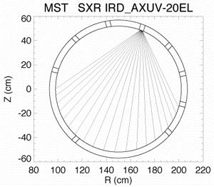
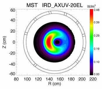
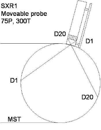
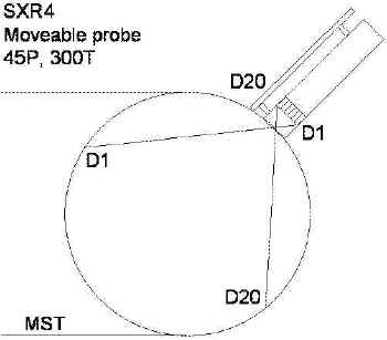
Description Proposed geometry of the lines of sight The SXR radiation is measured by a set of Si photodiodes, disposed on a linear support; an array of detectors is used for compactness. Be filters in front of the diodes are used for selecting only the SXR energy range (10 eV-10 keV). At the moment the best choice is the 20 diode array manufactured by IRD (an application of these photodiodes can be found in Boivin R L, et al., High resolution bolometry on the Alcator C-Mod tokamak, Rev.Sci.Instr. 70, 260 (1999)); the diodes are 0.75x4 mm, with an active area of 3 mm2. An example of the lines of sight is shown in the following figure: In this case the array is inserted in a porthole at a poloidal angle of 75º. In order to obtain a set of lines of sight viewing a region of the plasma more localised at the edge, the array can be inclined inside the probe (but only a few degrees, due to space constrictions). The angular aperture of the set of chords can be changed by modifying the distance between the array of detectors and the pinhole in front of the head (used to define the cone of sight, that is the solid angle of each chord). When this distance is 10 mm, as in the above figure, the impact parameters of the lines of sight lay between -35 and 35 cm, and the set of chords covers about the 70% of the MST poloidal cross section. The complete tomography system is composed by a set of four fans of chords, similar to that showed, and disposed in different poloidal portholes (all in the same toroidal location). The choice of the portholes has been an important issue and had to be made in such a way to cover as much uniformly as possible the poloidal cross section of the machine. With the above described geometrical layout, two consecutive cones of sight (the cone defined by one diode and the pinhole, and whose axis is considered as the line of sight) overlap up to the 50%. This was considered to be a problem for a tomographic reconstruction, and initially only every second detector, for each array, was used (thus reducing the number of diodes to 10). Several simulations of SXR measurements and reconstructions have been performed, showing that the overlapping of the cone of sight is not a problem provided the structure one wants to detect in the emissivity is larger than the cone of sight. In other words this means that the spatial resolution of the tomographic system is limited by the dimensions of the cones of sight. So all 20 diodes have been used for aech probe. The detailed description of the probe and the position of the array, Be filter, pinhole etc. can be found in here. Using a simple SXR model and the signals measured by other SXR diagnostic of MST, an estimate of the signals which will be obtained with the new diagnostic has been made. First, a SXR emissivity was simulated, considering only the bremsstrahlung component (no recombination and spectral lines was included in the model). Taking into account the formula of the bremsstrahlung, integrated in energy, 1.7 ne2 Zeff Sqrt(Te), with Te in eV, ne in 1019 m-3, there should be about 100 W/m2 of SXR radiation, measured along a central chord (length=1 m), at 400 kA and with ne=1019 m-3 and Zeff=2. If a beryllium (Be) filter of 12.5 micron is used the power will be between 10 and 20 W/m3, and the brightness is of the same order of magnitude. Finally, if the geometrical factor (that is the solid angle defined by the cone of sight, 9.5x10⁻⁹ m2, see also here) is taken into account, the power on the detector is about 0.5 mW. The current generated by the diode will be greater than 20-40 nA for a central chord, arriving at more than 100 nA with PPCD. An amplification gain of 107 should then be used. If the same SXR model is used to simulate the signals measured with the three filters SXR diagnostic (which was installed on MST on the summer 2000 for measuring the electron temperature in the plasma core by the double-filter technique), the experimental values are reproduced. The same calculations can be made with the same detector but without any Be filter, i.e. using the diode array as an array of bolometers (given the linear spectral response of the diodes in most of the XUV region). Considering a total radiated power of 1 MW, distributed on the whole plasma volume (7.4 m3), a density power of about 135 kW/m3 is obtained; again, with a chord 1 m long, the brightness is 135 kW/m2. Using the previous solid angle the power on the detector is of the order of 1.3 W, with a current of hundreds of mA. Simulation of tomographic reconstruction An important test of the diagnostic is the analysis of its capability to reconstruct a SXR emissivity distribution. Using the same SXR model considered in the previous section, a poloidally symmetric SXR emission has been simulated; then, a m=1 structure has been added, in order to evaluate what can be obtained with a limited number of lines of sight. This emissivity is shown (in a poloidal section) in this figure:
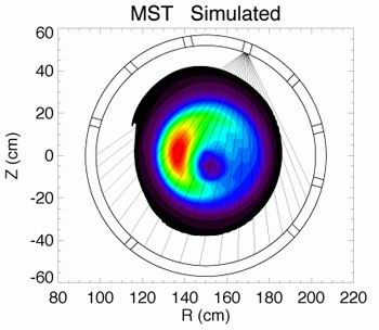
The simulated brightness has been calculated by integrating the emissivity along the 20 chords (the scheme described above of is used). Then, the reconstruction is performed using the simple Cormack-Bessel method [Franz P, et al., Nucl. Fusion 41, 695 (2001)]; in this case, due to the presence of only a single fan of lines of sight, only the m=0 and one m=1 (cosine) harmonic can be included. The result is displayed here:
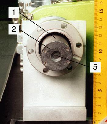
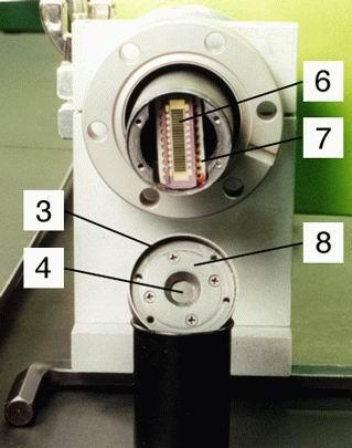
The m=1 structure is reconstructed, at the same poloidal position of the simulated one, and with similar radial and poloidal width. Even with only one fan of chords, this simple geometry should be capable to detect the presence of asymmetries in the SXR emissivity distribution; besides, the poloidal rotation of the magnetic modes, an effect often found in the MST plasma, should be helpful for the reconstruction of the actual shape and position of this structure. The installation of three or more probes, at different poloidal angles, greatly improves the "quality" of the tomographic reconstruction: fine details of the SXR emissivity and of structures could be resolved and analysed. The layout of the SXR probe head is showed in detail in these figures:
The numbers (1),(2), etc. refer to the pictures. It consists of an aluminium cylinder (1) closed by a cover (2),(3) (made of the same material) which contains the Be filter (4) and a thin stainless steel foil with the pinhole (5). The array of detectors (6) and its Teflon socket (7) are positioned d=1 cm away from the pinhole; the pinhole area Apin=4 mm2 and the active area of one detector is Adet=3 mm2 (see here for details on the array) so that the geometrical factor (solid angle) of one cone of sight is about 9.55x10⁻⁵ cm2. The removing of the top (2) allows the changing of the pinhole, the Be foil (12.5 micron of thickness) and/or the array of detectors in a very simply way, without touching the cables or any other part of the probe head. For the pinhole and Be one need only to separate the two components (3) and (8). The probe head is attached to a long tube (which contains all the cables) and then to the insertable system, through an adapter. This mechanical system has been adapted from the MST type of insertable system, used for positioning some magnetic probes.
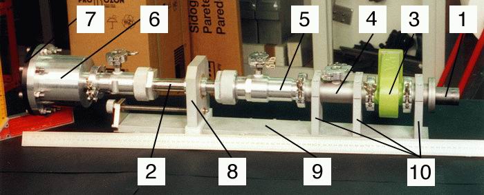
The insertable system is composed of various components (numbered from (1) to (10)) and allow to insert, extract or move the diagnostic, to place it in the measurement position and to rotate it (to change the orientation of the lines of sight from a poloidal fan (as indicated in figure) to a toroidal one). In the previous picture the probe (1) in its measuring position (with the pinhole 1 cm apart from the inner wall of the MST vacuum vessel) and is connected to the tube (2) through an adapter (not visible). The tube (and the attached probe) can be moved in the direction indicated by the arrow and slides inside the following components:
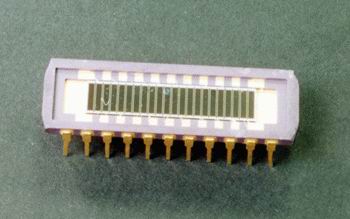
The final part (6) is rigidly connected to the tube and is closed by an insulating flange (7) where all the cables are extracted (with vacuum tight feedthrough). Each photodiode is read through a coaxial cable and a dedicated coaxial Fisher 00 connector. The remaining components (8),(9),(10) form the system which allow the translation and rotation of the tube (2) and of the probe head (1). The whole diagnostic will be evacuated through three holes, one in the "T" tube (4) (KF flange) and two adapters from NPT 1/4" to KF DN16 in the tube (5) and the rear part (6). These three ports will be connected together and pumped simultaneously with a single pump (the roughing vacuum system of MST). Actually the port in the rear part (6) has never been used. Since 2005-2006 all probes have been upgraded with Lemo bipolar feedthroughs and connectors and the insulating flange on SXR1 probe has been replaced by an aluminum one. The prototype will include the probe head and all the insertable system: in this way all kind of mechanical and electronic tests will be made possible; the measurement of the SXR profile using different pinhole areas or thickness of Be, in order to select the better values of these components, can be performed in a relatively simple manner. It is clear, however, that a tomographic system, composed by three or more probes, does not need any insertable system, but should be made by the probe head (1) inserted in the portholes in a fixed position, and directly connected to the vacuum vessel through a flange, where all the signals are extracted. Actually one of the SXR probe is fixed (SXR2) but this reveals itself as a limitation. Since January 2007 a new version of this probe, moveable, is being studied. The selected detector is model AXUV-20ELM from IRD.
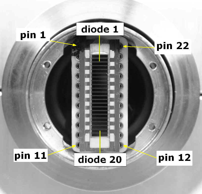
It has been chosen because of the flat response over the spectral region of interest (100-6000 eV, 35 microns effective silicon thickness), which make it convenient also for bolometry. It comprises 20 pixels, 4x0.75 mm2 each, in a common anode configuration. Shunt resistance is 300 MW and resistivity is 500-1000 W/cm. Capacitance is 1 nF if unbiased, but speed is limited by the bandwidth of the amplifier, due to the high gains. Dark current is 1 pA unbiased and < 100 pA with a bias of 5V, which is necessary to fully deplete the junction. A special version of the package has been ordered with smoothed corners for compatibility with the camera enclosure, which has to fit into a 38.1 mm diameter port. In this picture the pin layout of the AXUV-20ELM array is described. The pin 1 is always marked with a black spot on the teflon socket, and the pin are numbered as indicated, counterclockwise. Pin 1 is in the upper left side of the socket, viewing the array from above (as in the picture).
The first and the last diode in the array are "blind" ones, not connected to any pin. Below is the list of all pins and the corresponding diodes.
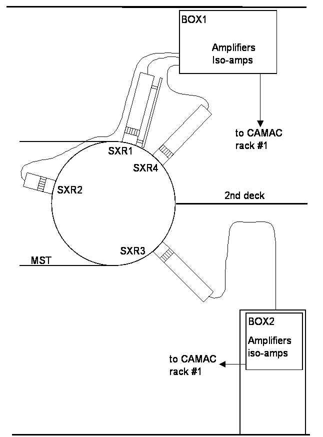
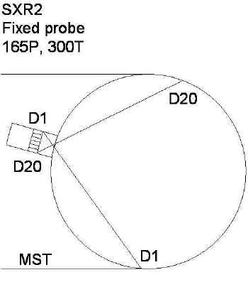
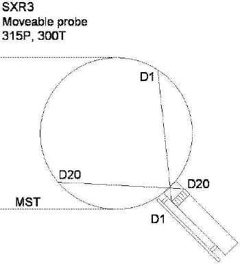
From simulations and comparison with past measurements on MST, in standard discharges we expect signals of the order of 10 nA on central cords, about 1 nA in the external chords. High confinement regimes have a significantly higher signal level. The noise behaviour of the chosen detector seems to be adequate for such signal levels. In the detector manufacturers investigation other solutions have been also considered. UDT produces detectors for soft x-rays with flat response, but only single channel. The y have been used in August 2004, not giving any improvement with respect to the IRD diodes. Ortec EG&G, now Perkin Elmer, instead has proposed a custom array detector, 10 channels (8x1.8 mm2 each pixel), which fits into the MST 38.1 mm ports, b ut has not been considered. This picture shows the tomography final layout. Four probes have been installed, three moveable (SXR1 @ 75P, SXR3 @ 315P and SXR4 @ 45P) and one fixed (SXR2 @ 165P), all in the same poloidal section (300T). The lines of sight of the probes are the following:
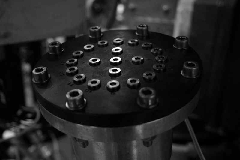
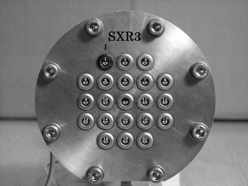
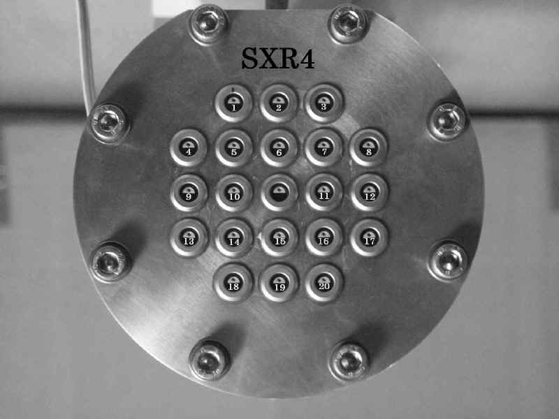
This layout can be downloaded as a word file or a pdf. A better view of the four probes, of the lines of sight and an example of the measured brightness profiles can be downloaded here (pdf). Vacuum Feedthrough and Flanges Concerning ultra high vacuum feedthroughs connections, a single channel solution has been preferred for the prototype SXR1, in order to minimise electrical cross-talk on the connector: Fischer coaxial connectors, one for each pixel, are mounted on an insulating fibreglass flange. Then this flange has been replaced with a new one, made of aluminum, with 21 Lemo bipolar feedthrough. The SXR2 probe (fixed version) was initially equipped with a multipin connector from Caburn. After one and a half year this flange was replaced (on September 2003) with a custom made flange equipped with 14 Lemo bipolar feedthrough. The use of a feedthrough for each diode seems better, both for cross talk and flexibility. The SXR3 and SXR4 probes have also been designed with the same Lemo feedthrough (21 each probe). The following pictures shows the flanges of the SXR diagnostics. Each number indicates the diode connected to that feedthrough.
The electric connections in the SXR2, SXR3 and SXR4 flanges are the following:
The complete set of drawings of the SXR tomography can be found in this page. The list of drawings is in this text file. Amplifiers should fulfil the following requirements:
First test of the detector combined with a variable gain amplifier from Femto has shown that both noise and speed are not affected by applying a bias voltage. It will then be required only if necessary to extend the energy range. An indicative table of rms noise in different bandwidth-gain configurations provide a first idea of possible performance:
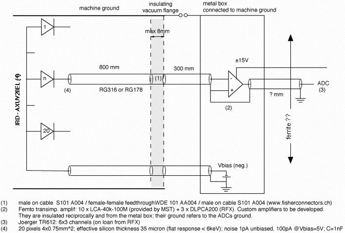
Rise time is not less than 1 msec at maximum available bandwidth. We proposed to use temporarily 10 Femto amplifiers (gain=108, bandwidth=40 kHz), already available at MST, for the first campaign with the prototype camera, plus 3 variable gain Femto amplifiers from RFX. We contacted a local company (Elad) to build the final amplifiers, but we also considered to have them built at MST, using G.Fiksels' or M.Reyfman's design. The contract discussed with Elad was to develop a single channel amplifier first, starting from the scheme the used for the avalanche photodiode amplifiers they developed for the Thomson scattering diagnostic of RFX. A 10 channels amplifier would then be engineered, with the possibility to mount it directly on the vacuum flange with a multipin connector. See also this page for a description of the electric layout of the SXR tomography. A schematic layout is presented below:
The picture shows how the grounding could be arranged, in order to have a compromise between shielding the signals and avoiding ground loops. After almost three years of operations and tests the best solution is to ground the diode array directly to the probe, using the two screws which fix in position the teflon socket; the ground of the circuit will be on turn the MST vessel, namely the machine ground. To avoid shorting the machine ground with the CAMAC ground, isolated amplifiers are used after the TLA modules. For the SXR2, SXR3 and SXR4 probes the following layout is used for grounding:
"1" and "2" are the two screws; pin 1 and pin 12 are the pin of the teflon socket of the common anode of the AXUV-20ELM. Basically the coaxial cables are divided in two groups. In each group all the shields are connected together. Then the shields are connected to one pin and one screw, or the other pin and the other screw. The screw 1 is close to pin 1, screw 2 to pin 12. In particular, group A and B are formed by the diodes:
For SXR1 a sligthly modified grounding has been used for a few time. For this probe the screws 1 and 2 are hooked up to the pin 1 and 12, resp. (as for the other probes), but all the shileds of the coaxial cables are soldered together in a unic group, which is then wired only to one pin, pin 12. This was the layout used in April 2003, and the first test to try to reduce the pickup noise in the signals (before that date the array was not grounded in the probe, but in the rear flange, and the wires from pin 1,12 to screws 1,2 were not present). We kept this layout only to make a comparison with the new layout of the SXR2,3,4 probes.
All the SXR1 and SXR2 diodes not used are grounded (hooked up to the common anode) directly in the socket. Since 19-Oct-2006 also SXR1 uses the same grounding layout of the remainig probes so that now all probes have the same layout. Up to twenty channels are required for each detector array. Main specifications are:
We have identified three possible solutions:
The approach we suggested was to perform the first campaign with the prototype system (last term 2001) using 4 Joerger 612/3 CAMAC modules on loan from RFX, which cover one detector, and based on this experience, evaluate the most convenient permanent solution. These CAMAC modules have already drivers for the MDS software environment and have already been used in MST. The 4 TR612/3 have been used for SXR1 and SXR2 until August 2004, then a new system of five Joerger TR1612 (16 channels per module) has been installed. The total number of channels is 16x5=80, enough for the present diagnostic. |
||||||||||||||||||||||||||||||||||||||||||||||||||||||||||||||||||||||||||||||||||||||||||||||||||||||||||||||||||||||||||||||||||||||||||||||||||||||||||||||||||
| Home | Description | Electronic layout | User manual | Manuale | Info | Images | Results | History | Logbooks | Bibliography | Links |